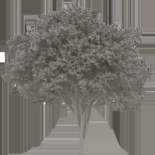
There came a question if it is possible to create rock and stone models in Silvador. It actually wasn't, but it makes a good sense to allow that: Just like plants, shape of stones is driven by controlled randomness to big extent. Just like plant models, also stone models can benefit from easy LOD creation and shading precalculated in textures. Therefore version 1.54 comes with extension of Volume component that allows that.
The Volume component on its own allows creation of closed geometry and one can produce shapes like this:
In 1.54 there is something new: There are new attributes hNoiseOctaves and array hNoiseAmplitude. By using those it is possible to apply cascade noise on position of the volume vertices. hNoiseAmplitude is an array that allows controlling of individual frequencies, thus it is possible to apply just low frequencies:
... or just high frequencies:
... or all frequencies:
... which is already not that far from what we want to achieve - a stone.
So much about shape. But there came a bigger challenge - texture mapping.
For convenience of artists and to respect existing infrastructure in usual game engines, we must apply 2D texture on the surface. The default mapping of Volume component is Cylindrical mapping. Unsurprisingly, it is producing 2 ugly singular points on typical stone, like this:
After number of experiments f.i. with triplanar mapping, we settled with something called Conic mapping, where top and bottom hemisphere is mapped with the same but mirrored texture. This is how it started to look:
User can choose between those 2 mappings by a new attribute projectionType. The above conic mapping is also not an ultimate solution. It transfers the singular point artifacts to mirror artifacts like this:
But that is already something we can fight with. The same way we apply noise to height of given vertex, we can also move it forward and to the side and hide the mirroring. Attributes that control that are called uNoiseOctaves, uNoiseAmplitude, vNoiseOctaves and vNoiseAmplitude. This is what we get then:
Few results with applied lighting:
Sunday, June 30, 2019
Thursday, September 21, 2017
Flowers and blossoms
Version 1.53 of Silvador comes with improvements, that allow creation of complicated plant structures such as flowers or blossoms. Mainly two new structural components are behind this improvement. They are called Hydra and Urchin.
Hydra
Hydra component does not generate any geometry on its own, but is able to spawn in a controlled way generation of descendants located in a circle. With almost default parameters the component can produce a structure like this:
Apart of number of descendants and if they are spawned along the whole circle or just in an arc, it is also possible to control their type, probability and orientation with rich set of parameters. Using Hydra component it is possible to describe f.i. petals. If we play with that a bit, we can already create believable blossoms, like this:
This particular blossom we can find among templates coming with Silvador and it can be a good starting point for many types of blossoms.
Urchin
Similar to Hydra, Urchin component also spawns descendants in an organized way. This time the descendants are filling a disc in a hexagonal shape, typical in natural structures. By default Urchin component produces structures like this:
It can be used to describe inner of the blossom - florets (f.i. inner circle of the sunflower). Number of attributes come with Urchin. Apart of density and size of the disc we can also control profile of the disc itself. Note that many attributes including the profile are defined as a curve, addressed by the distance from center.
Examples
All the following examples were created in Silvador with help of the above components. Some of those are present in the gallery distributed with Silvador.
Tuesday, September 19, 2017
Improving normal map on billboards
To enhance lighting of objects in dynamic virtual environments, maps that contain information about normal of every texel of a surface of a model are being created. Those are called normal maps. Silvador also generates normal maps. They look like this:
If we look at the trunk, it looks fine, there is not much to be improved - it just matches the geometry the texture represents. But if we look at the crown that consist of more-or-less randomly rotated leaves, its worse - there just appears to be something that resembles a white noise. There is no structural information about the crown whatsoever. And if we use it for shading, the result corresponds to that, it is flat. If there would not be for the trunk, we couldn't say what direction a light is coming from.
In Silvador since version 1.53 there is a new option, by default on for billboards, it is called VisualizerLOD2.polyplaneCrownAwareNormalMap. It influences the way normal map is calculated. It also considers original normal of a leaf just as the original approach, but weights it by the visibility of given point from given direction. That means that normals tend to point more to direction they are visible from. We calculate the adjusted normal iteratively using this formula:
M = normalize(sum(for x from <0, n>)(shadowCoef * max(dot(N, Lx), 0) * Lx))
, where:
N - normal vector of the surface
L1..Ln - individual vectors of light contribution (possibly shaded)
M - adjusted normal, respecting visibility of given point
The difference is significant. Following 2 images demonstrate difference without and with the crown-aware normal map:
There is suddenly much more low-frequency information present in the normal map. Normals on the left side of the crown tend to point left and on the right side to the right. This is what will give the tree crown a spherical shape after lighting is applied. This is how you can see the result lit in the virtual environment of VBS Blue (original normal map, crown-aware normal map):
If we look at the tree crown on the right image, we don't have a problem to identify what direction is light coming from, unlike the left image.
Overview of generated maps
Let's recapitulate what all maps Silvador can generate at the moment:
Albedo RGB / Alpha:
Macro RGB / Alpha:
Normal:
Sunday, April 16, 2017
Enhancing visual quality of billboards
For real-time rendering it is essential to be able to simplify model geometry down to units of triangles. This simplified version is either a set of perpendicular faces (we call it a polyplane), or one face rotating towards the camera position (we call it a billboard). In this article we focus on such geometry and show examples of billboards, but it applies to polyplanes too.
Quality of the billboard texture is very important: Some real-time environments render just those, even on close. Other engines use 3D models on close, but they usually want to switch to billboards as soon as possible, usually quicker than other objects. In general, plant billboards are being rendered at very close distance in most of the cases. Their quality matters.
Using ExporterProxy component, we can simplify the geometry down to one polyplane and generate a model that looks like this:
Consequently we can put such manually created model (polyplane) on top of a tree structure like this:
And we get a final model like this:
Note the bright sides - we have a complex model of a tree simplified down to reasonable number of triangles (18044) for rendering and we have the shape of polyplanes fully under control.
These artifacts are very well visible on the final output.
Silvador since version 1.53 supports automated generation of both mentioned versions during proxy model generation. It puts them as two separated lods of generated model. It is being controlled through argument ExporterProxy.generateDetail.
This is how the problem and the solution looks like in the realtime environment:
Quality of the billboard texture is very important: Some real-time environments render just those, even on close. Other engines use 3D models on close, but they usually want to switch to billboards as soon as possible, usually quicker than other objects. In general, plant billboards are being rendered at very close distance in most of the cases. Their quality matters.
Manual polyplanes
Let's take a small detour: In Silvador, if we don't want to rely on automated geometry simplification (automated polyplanes), we don't have to. We can model one or more types of branch ends, the geometry in full detail can look like this:Using ExporterProxy component, we can simplify the geometry down to one polyplane and generate a model that looks like this:
Consequently we can put such manually created model (polyplane) on top of a tree structure like this:
And we get a final model like this:
Note the bright sides - we have a complex model of a tree simplified down to reasonable number of triangles (18044) for rendering and we have the shape of polyplanes fully under control.
The problem
And now the dark side. When we want to create a billboard texture from such a geometry, we have a problem. The polyplane simplification is too visible in the output. In general there are 2 types of problems: One is, that polyplanes that are in too sharp angle to camera view form a line-like artifacts. Another one is, that polyplanes tend to have too uniform lighting on them, even though normal map is applied. The macro texture looks like this:These artifacts are very well visible on the final output.
The solution
There is a way out of this. The main problem is, that we use simplified geometry for rendering into billboard. And we don't have to. The manual polyplane is defined up to leaf level. When we generate model out of it, we can generate 2 versions: One the usual geometry simplification down to one polyplane, second the original full geometry generated up to leaf. First is used for producing 3D geometry with polyplanes of reasonable number of triangles, second is used for billboard shading. It makes the shading more demanding as there are going to be millions of triangles to render, but as it is happening offline, it is a small price to pay. And the output looks like this:Silvador since version 1.53 supports automated generation of both mentioned versions during proxy model generation. It puts them as two separated lods of generated model. It is being controlled through argument ExporterProxy.generateDetail.
This is how the problem and the solution looks like in the realtime environment:
Thursday, February 12, 2015
Polyplanes and rendering performance
Polyplanes allow us to have an absolute control over final number of triangles of generated model. In other words, we can choose arbitrary number and create model with number of triangles that doesn't cross that number, thanks to polyplanes. But performance of real-time application is determined also by other factors than number of triangles, like the number of drawn pixels.
Number of drawn pixels of model depends on many parameters irrelevant to the actual model, like its orientation on screen, distance from camera if perspective is used or screen resolution. For simplification, instead of number of drawn pixels let's start talking about surface area of model from now on. It can be proven that in case of a mesh soup they are linearly dependent.
This table brings rather bad news. We decrease the number of triangles from 10k to 5k, but we still draw 85% of original pixels instead of expected 50%. To draw 50% of original pixels, we'd need to decrease number of triangles from 10k to 1k. Reason for that is, that while number of polyplanes is decreasing with number of triangles roughly linearly, their size is increasing, keeping the total surface area still high.
But problem is not only with the ratio the surface area is decreasing, but with the total surface area in finer and medium LODs. It was tested that even on not too old GPU like GeForce GTX 560 the performance of tree models with more than 20000m2 is questionable.
The surface area heavily depends on tree shape and we don't have to solve this issue for every tree model. The following images illustrate two very different kinds of tree. Note that while the first fine model has 10 times more triangles than the second coarse one, its surface area is about 5 times smaller. And indeed, the rendering performance of the first one is significantly better on modern HW than the second one.
We basically need a mechanism that allows us to decrease the surface area. Most of the pixels on tree go to polyplanes, let's focus on those.
Small intermezzo: surface area is not the only problem of polyplanes. As we try to reduce number of unique polyplanes (it was described in previous blog post), it often happens, that we see polyplanes of the same shape very close to each other. It looks like this:
This is because they start shortly after branching, and as they have similar properties, the polyplane manager decides to give them the same texture. Obviously this doesn't bring any good for the final result and it would be better if this duplication is not there.
The following sequence shows result of polyplane reduction and in the end compensation for thinner crown. Bottom images show corresponding heat-map visualizing overdraw. First image shows original model. You can see it has surface of more than 28000m2 and 571 polyplanes. You can also see visual artefact described earlier at its botom branches. Second and third image show polyplane reduction to 400 and 200 with surface area reduction to 20000m2 and 10000m2. You can observe the crown of the third image is already visibly thinner comparing to first image. On fourth image we compensate the thinner crown by increasing density in branch tips - through controller Branch3.branchDensity. Note the surface area of model increased to 17000m2, because the density increase described in previous step leads to increasing size of polyplanes. However, in total we decreased the surface area from 28000m2 to 17000m2 while keeping the same tree density and as a bonus we removed the visual artefact.
When configuring exporter, it is definitely worth watching surface area of model to be generated. If there is higher number like 15000, 20000 or more, consider taking steps that can reduce the total surface area. (the numbers need to be biased with the engine the trees are used in - some engines can have more, others less complex pixel shaders. Provided numbers are relevant to VBS3.)
Number of drawn pixels of model depends on many parameters irrelevant to the actual model, like its orientation on screen, distance from camera if perspective is used or screen resolution. For simplification, instead of number of drawn pixels let's start talking about surface area of model from now on. It can be proven that in case of a mesh soup they are linearly dependent.
Problem
One might think that if we reduce the number of final triangles to half, we also reduce its surface area to half, right? Well, not exactly. Look at the following table that shows on particular example of Quercus tree dependency of surface area on number of triangles.This table brings rather bad news. We decrease the number of triangles from 10k to 5k, but we still draw 85% of original pixels instead of expected 50%. To draw 50% of original pixels, we'd need to decrease number of triangles from 10k to 1k. Reason for that is, that while number of polyplanes is decreasing with number of triangles roughly linearly, their size is increasing, keeping the total surface area still high.
But problem is not only with the ratio the surface area is decreasing, but with the total surface area in finer and medium LODs. It was tested that even on not too old GPU like GeForce GTX 560 the performance of tree models with more than 20000m2 is questionable.
The surface area heavily depends on tree shape and we don't have to solve this issue for every tree model. The following images illustrate two very different kinds of tree. Note that while the first fine model has 10 times more triangles than the second coarse one, its surface area is about 5 times smaller. And indeed, the rendering performance of the first one is significantly better on modern HW than the second one.
We basically need a mechanism that allows us to decrease the surface area. Most of the pixels on tree go to polyplanes, let's focus on those.
Small intermezzo: surface area is not the only problem of polyplanes. As we try to reduce number of unique polyplanes (it was described in previous blog post), it often happens, that we see polyplanes of the same shape very close to each other. It looks like this:
This is because they start shortly after branching, and as they have similar properties, the polyplane manager decides to give them the same texture. Obviously this doesn't bring any good for the final result and it would be better if this duplication is not there.
Solution
In version 1.49 of Silvador there comes tool, that can help with both problems described above at once. We can limit the total number of polyplanes. It is being controlled by new attribute VisualizerLOD2.polyplaneReductionTotalWantedCount. We obviously need to use this mechanism carefully, the polyplane reduction makes the crown thinner. Either we can accept it, or we need to compensate it f.i. by making tips of branches denser when describing given LOD, see Branch3.branchDensity and VisualizerLOD2.modify.The following sequence shows result of polyplane reduction and in the end compensation for thinner crown. Bottom images show corresponding heat-map visualizing overdraw. First image shows original model. You can see it has surface of more than 28000m2 and 571 polyplanes. You can also see visual artefact described earlier at its botom branches. Second and third image show polyplane reduction to 400 and 200 with surface area reduction to 20000m2 and 10000m2. You can observe the crown of the third image is already visibly thinner comparing to first image. On fourth image we compensate the thinner crown by increasing density in branch tips - through controller Branch3.branchDensity. Note the surface area of model increased to 17000m2, because the density increase described in previous step leads to increasing size of polyplanes. However, in total we decreased the surface area from 28000m2 to 17000m2 while keeping the same tree density and as a bonus we removed the visual artefact.
When configuring exporter, it is definitely worth watching surface area of model to be generated. If there is higher number like 15000, 20000 or more, consider taking steps that can reduce the total surface area. (the numbers need to be biased with the engine the trees are used in - some engines can have more, others less complex pixel shaders. Provided numbers are relevant to VBS3.)
Saturday, February 7, 2015
Polyplanes and visual quality
Geometry of tree model prepared for real-time rendering is split between original geometry (usually trunk area) and polyplanes (usually leaf area). Polyplane is a simple geometry approximation of original tree structure with help of texture where is projected original tree structure. Polyplanes are one of the most important ways how to simplify geometry between individual levels of detail in Silvador - the rougher the LOD, the closer to root its polyplanes start.
While polyplanes are a powerful tool for geometry simplification, there are few aspect we need to be aware of, for getting the best possible result. In this blog post let's focus on visual quality of polyplanes.
This is what individual entries tell us about plant model:
While polyplanes are a powerful tool for geometry simplification, there are few aspect we need to be aware of, for getting the best possible result. In this blog post let's focus on visual quality of polyplanes.
Model statistics
But first let's look at meaning of tree model statistics. Statistics is positioned in bottom right corner of the preview window and looks like this:This is what individual entries tell us about plant model:
- heig - Height of the geometry of the tree model in meters. Note that it is really the geometry what is measured, not what is in the textures. This means that f.i. the tree model on the image above reports higher number than what is actually visible - it reports corner of the polyplane geometry, not area where alpha of polyplane texture is non-zero.
- surf - Surface area of geometry, in square meters.
- tris - Number of triangles the model consists of.
- poly - Number of unique polyplanes. / Total number of polyplanes.
Texture quality vs Crown shape fidelity
Very important counter for the final model visual quality is the number of unique polyplanes. It can be well controlled through VisualizerLOD.polyplaneReductionWantedCount controller. In usual cases it corresponds to minimum value between polyplaneReductionWantedCount and total number of polyplanes. In special cases where polyplanes are generated from components of different kind, the final number of unique polyplanes can be higher than polyplaneReductionWantedCount. For the best quality of the final model it is important to find the balance between final texture resolution and geometry fidelity. Consider the following sequence of images demonstrating various setting of polyplaneReductionWantedCount for the same model:
On the first image we chosen to have only 2 unique polyplanes. Note the geometry is degraded a lot from the desired result (bottom image). On the other hand the generated texture (on the right side) is very detailed. On the last image we have the opposite, the best possible polyplanes - each one is unique. On the other hand each one occupies space in the final UV atlas texture. Therefore we now have a worse quality of textures as more textures need to fit in. On the middle image we chosen something in between - 3 target unique polyplanes. Its clearly the winner in this particular case - the shape of tree is very close to the last image while detail of texture is very close to the first image.
When configuring exporter, it is definitely worth spending few moments with polyplaneReductionWantedCount controller and find smallest possible number when you are still happy with the tree shape.
Subscribe to:
Posts (Atom)